With their aerodynamic shape, rockets seem to “effortlessly” push through the atmosphere as they accelerate to Space. But without any type of wing or tail structure, it can be hard to grasp how they change direction.
During launch and ascent, rockets primarily use a gimbaled thrust system, which swivels the engine nozzle on two axes to change direction and rotate. In Space, it uses a Reaction Control System, utilizing reaction wheels, gyroscopes, and smaller thrusters for directional and orientational maneuvers.
We commonly associate the ability to fly and steer in the air with a vehicle equipped with a wing structure (or rotors in the case of a helicopter). As a result, a rocket able to maneuver into space without any shape resembling a conventional aircraft can be hard to understand.
The reason rockets and conventional aircraft have such different structures is that they use propulsion and steering mechanisms designed to operate in different environments, and the systems they use to function are based on different principles.
An aircraft utilizes the air in the atmosphere to stay airborne (through a force called lift, where the air flowing underneath an airplane’s wings pushes it up) and also to change direction. An atmosphere with a substantial air density is required for any conventional aircraft to function.
A rocket, though, mainly operates in space, and the time and distance spent in Earth’s atmosphere are too short to make effective use of the drag provided by the air to steer.

Instead, it primarily relies on Newton’s Third Law of Motion for maneuvering a rocket into and through space via a system called gimbaled thrust.
How Gimbaled Thrust Works To Steer A Rocket
Since a rocket does not make use of atmospheric air to fly or change direction, it requires another means of propulsion to move and steer than conventional aircraft. This is where Newton’s Third Law of Motion comes into play.
It formally states that “For every action, there is an equal and opposite reaction.” All rockets destined for space travel function/operate on this principle of two opposing forces.
The first force that comes into play is the thrust created by the rocket’s engine as it pushes the hot gases out the rear through the nozzle. The thrust from the gases creates the second force, which propels the vehicle forward as a reaction.
(To learn more about what exactly a rocket is and how it works, read the full article here.)
The thrust created by the rocket’s engine explains how a rocket is propelled forward, but not how it is able to steer and change direction while still in the atmosphere. For this type of maneuvering, a system called gimbaled thrust is utilized.
Gimbaled thrust is a system that uses thrust vectoring to change the direction a rocket is traveling in by swiveling the engines’ nozzles on two axes, which allows the vehicle to rotate around its center of gravity to make necessary course adjustments.
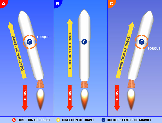
The illustration above provides a visual explanation of how this system works in practice using three theoretical scenarios:
- Section A describes a scenario where a rocket needs to make a course correction to the left. Swiveling the rocket nozzle left allows the vehicle to rotate through its center of gravity until it points in the desired direction, after which the nozzle straightens, and the rocket is traveling in the newly adjusted heading.
- Section B describes a scenario where a rocket needs no course correction. By keeping the rocket nozzle straight, the thrust and vehicle orientation are in the same direction, allowing the vehicle to continue on its current heading.
- Section C describes a scenario where a rocket needs to make a course correction to the right. Swiveling the rocket nozzle right allows the vehicle to rotate through its center of gravity until it points in the desired direction, after which the nozzle straightens, and the rocket is traveling in the newly adjusted heading.
Needless to say, thrust vectoring via gimbaled thrust involves a lot more complex mechanisms and processes than illustrated in the diagram above. However, it highlights the key principles responsible for allowing gimbaled thrust to propel and steer a rocket.
Gyroscopic and other sensors form part of a rocket’s guidance system, which lets it know what orientation the vehicle is in and the direction it is traveling at all times. Whenever it needs to make any directional change, it does so primarily through gimbaled thrust.

Although gimbaled thrust is used almost exclusively in modern rockets to steer and change direction while traveling through the atmosphere, other mechanisms were used in the past, and some are still used today in specific applications:
- One of the earliest methods of directional control on a rocket was through exhaust valves placed at the exit of the thruster’s nozzle. By changing the angle of the valves, the flow of the exhaust gases was modified, allowing the rocket to steer and rotate.
- Another form of maneuvering is through propellant injection used in solid propellant rockets, where injectors situated around the back of the engine inject fuel into selective areas of the flow system to adjust direction. This technique was mainly used in ballistic missiles.
- One type of rocket maneuvering still used today is the utilization of vernier thrusters. These small auxiliary thrusters are usually placed next to the main rocket thrusters and fired selectively to change a rocket’s direction. The vernier thrusters on Soyuz rockets are an excellent example of the effective use of this form of directional control.
Apart from mechanisms and systems situated within a rocket, external factors are also used to assist with navigation and directional control. One such factor is the use of Earth’s gravity to help with the rocket ascent and establish its trajectory.
Shortly after launch, a rocket performs what is known as a gravity turn. It rotates until it is in the correct orientation, after which it starts to pitch over in the direction of the planned trajectory. It uses Earth’s gravity to follow this trajectory while the rocket is still accelerating.
(While traveling in space, spacecraft also use the gravitational forces of nearby planets and large satellites to make course corrections and orbital maneuvers.)
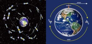
How A Rocket Maneuvers In Space

When a rocket enters space, it is already following the vehicle’s planned trajectory. This simply means it is already traveling at the desired speed and heading in the correct direction to complete its mission.
Any speed or course correction at this point requires only incremental adjustments with smaller mechanisms. Depending on its size and momentum, it may take longer to maneuver a vehicle in space, but the tiniest force will have a significant impact in the vacuum of space.
As a result, a spacecraft uses navigational systems like an Orbital Maneuvering System (OMS) or Reaction Control System (RCS), which utilize small rocket thrusters strategically placed around the vehicle to perform small maneuvers like propulsion, rotation, and reorientation.
Typical maneuvers that may require the firing of these small thrusters include slowing the vehicle down, correcting drift, moving to a higher/lower orbit, and positioning/orienting a spacecraft for docking with another object (like the International Space Station).
For example, the retro rockets situated in the nose of a spacecraft are typically used to slow the vehicle down, while attitude control thrusters placed on the side of the craft are used to change the craft’s orientation and make minor course corrections.
These auxiliary thrusters don’t need to be very powerful or fire for long periods since they are used for tiny adjustments in short bursts. As a result, they don’t need a lot of fuel, which usually consists of cold gases like helium and nitrogen.
Sometimes, a propellant mixture called hypergolic fuel is used in these smaller thrusters since they spontaneously combust when combined and do not need a separate oxidizer or ignition mechanism, making them ideal for use in space.
(These fuels are highly toxic, though, and can have a significant environmental if a rocket explodes in the atmosphere. Consequently, they are primarily used in the upper stages of a launch vehicle and the control thrusters of craft operating in space.)
Another mechanism that is also used for maneuvering a vehicle in space is called a reaction wheel. It is a type of flywheel spun at high speed in a spacecraft. Accelerating or braking the wheel changes the momentum, which forces the vehicle to rotate.
Multiple reaction wheels can be used in a spacecraft to allow it to rotate and adjust orientation on all three axes. This system also operates on Newton’s Third Law of Motion, which enables it to move a spacecraft by simply changing the momentum of the wheels.
(Learn more about exactly what Reaction Control Systems are, how they work, and the different situations in which they are deployed in this article.)
Conclusion
As illustrated in this article, a rocket moves and changes direction by using propulsion systems based on Newton’s Third Law of Motion. Chemical rocket engines are the preferred mode of propulsion due to the amount of thrust they produce.
They are able to maneuver and change direction in the atmosphere by using a process called thrust vectoring through a system called gimbaled thrust. This system is also used in space, although more precise systems like OMS & RCS are used, utilizing smaller auxiliary thrusters.
This article was originally published on headedforspace.com. If it is now published on any other site, it was done without permission from the copyright owner.